пятница, 10 февраля 2017 г.

Как работает NAT на Cisco ASA v9.1


NAT Rule Order

Network object NAT rules and twice NAT rules are stored in a single table that is divided into three sections. Section 1 rules are applied first, then section 2, and finally section 3, until a match is found. For example, if a match is found in section 1, sections 2 and 3 are not evaluated. Table 3-1 shows the order of rules within each section.

Table 3-1 NAT Rule Table


Table Section


Rule Type


Order of Rules within the Section
Section 1
Twice NAT
Applied on a first match basis, in the order they appear in the configuration. Because the first match is applied, you must ensure that specific rules come before more general rules, or the specific rules might not be applied as desired. By default, twice NAT rules are added to section 1.
Note If you configure EasyVPN remote, the ASA dynamically adds invisible NAT rules to the end of this section. Be sure that you do not configure a twice NAT rule in this section that might match your VPN traffic, instead of matching the invisible rule. If VPN does not work due to NAT failure, consider adding twice NAT rules to section 3 instead.
Section 2
Network object NAT
If a match in section 1 is not found, section 2 rules are applied in the following order, as automatically determined by the ASA:
1. Static rules.
2. Dynamic rules.
Within each rule type, the following ordering guidelines are used:
a. Quantity of real IP addresses—From smallest to largest. For example, an object with one address will be assessed before an object with 10 addresses.
b. For quantities that are the same, then the IP address number is used, from lowest to highest. For example, 10.1.1.0 is assessed before 11.1.1.0.
c. If the same IP address is used, then the name of the network object is used, in alphabetical order. For example, abracadabra is assessed before catwoman.
Section 3
Twice NAT
If a match is still not found, section 3 rules are applied on a first match basis, in the order they appear in the configuration. This section should contain your most general rules. You must also ensure that any specific rules in this section come before general rules that would otherwise apply. You can specify whether to add a twice NAT rule to section 3 when you add the rule.
For section 2 rules, for example, you have the following IP addresses defined within network objects:
192.168.1.0/24 (static)
192.168.1.0/24 (dynamic)
10.1.1.0/24 (static)
192.168.1.1/32 (static)
172.16.1.0/24 (dynamic) (object def)
172.16.1.0/24 (dynamic) (object abc)
The resultant ordering would be:
192.168.1.1/32 (static)
10.1.1.0/24 (static)
192.168.1.0/24 (static)
172.16.1.0/24 (dynamic) (object abc)
172.16.1.0/24 (dynamic) (object def)
192.168.1.0/24 (dynamic)

NAT Interfaces

You can configure a NAT rule to apply to any interface (in other words, all interfaces), or you can identify specific real and mapped interfaces. You can also specify any interface for the real address, and a specific interface for the mapped address, or vice versa.
For example, you might want to specify any interface for the real address and specify the outside interface for the mapped address if you use the same private addresses on multiple interfaces, and you want to translate them all to the same global pool when accessing the outside.

Mapped Addresses and Routing

When you translate the real address to a mapped address, the mapped address you choose determines how to configure routing, if necessary, for the mapped address.
See additional guidelines about mapped IP addresses in “Configuring Network Object NAT,” and Chapter5, “Configuring Twice NAT”
See the following mapped address types:
  • Addresses on the same network as the mapped interface.
If you use addresses on the same network as the mapped interface, the ASA uses proxy ARP to answer any ARP requests for the mapped addresses, thus intercepting traffic destined for a mapped address. This solution simplifies routing because the ASA does not have to be the gateway for any additional networks. This solution is ideal if the outside network contains an adequate number of free addresses, a consideration if you are using a 1:1 translation like dynamic NAT or static NAT. Dynamic PAT greatly extends the number of translations you can use with a small number of addresses, so even if the available addresses on the outside network is small, this method can be used. For PAT, you can even use the IP address of the mapped interface.

Note If you configure the mapped interface to be any interface, and you specify a mapped address on the same network as one of the mapped interfaces, then if an ARP request for that mapped address comes in on a different interface, then you need to manually configure an ARP entry for that network on the ingress interface, specifying its MAC address (see the arp command). Typically, if you specify any interface for the mapped interface, then you use a unique network for the mapped addresses, so this situation would not occur.

  • Addresses on a unique network.
If you need more addresses than are available on the mapped interface network, you can identify addresses on a different subnet. The upstream router needs a static route for the mapped addresses that points to the ASA. Alternatively for routed mode, you can configure a static route on the ASA for the mapped addresses, and then redistribute the route using your routing protocol. For transparent mode, if the real host is directly-connected, configure the static route on the upstream router to point to the ASA: specify the bridge group IP address. For remote hosts in transparent mode, in the static route on the upstream router, you can alternatively specify the downstream router IP address.
  • The same address as the real address (identity NAT).
The default behavior for identity NAT has proxy ARP enabled, matching other static NAT rules. You can disable proxy ARP if desired. Note : You can also disable proxy ARP for regular static NAT if desired, in which case you need to be sure to have proper routes on the upstream router.
Normally for identity NAT, proxy ARP is not required, and in some cases can cause connectivity issues. For example, if you configure a broad identity NAT rule for “any” IP address, then leaving proxy ARP enabled can cause problems for hosts on the network directly-connected to the mapped interface. In this case, when a host on the mapped network wants to communicate with another host on the same network, then the address in the ARP request matches the NAT rule (which matches “any” address). The ASA will then proxy ARP for the address, even though the packet is not actually destined for the ASA. (Note that this problem occurs even if you have a twice NAT rule; although the NAT rule must match both the source and destination addresses, the proxy ARP decision is made only on the “source” address). If the ASA ARP response is received before the actual host ARP response, then traffic will be mistakenly sent to the ASA (see Figure 3-14).
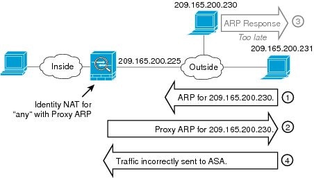
Figure 3-14 Proxy ARP Problems with Identity NAT

In rare cases, you need proxy ARP for identity NAT; for example for virtual Telnet. When using AAA for network access, a host needs to authenticate with the ASA using a service like Telnet before any other traffic can pass. You can configure a virtual Telnet server on the ASA to provide the necessary login. When accessing the virtual Telnet address from the outside, you must configure an identity NAT rule for the address specifically for the proxy ARP functionality. Due to internal processes for virtual Telnet, proxy ARP lets the ASA keep traffic destined for the virtual Telnet address rather than send the traffic out the source interface according to the NAT rule. (See Figure 3-15).
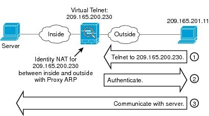
Figure 3-15 Proxy ARP and Virtual Telnet

Transparent Mode Routing Requirements for Remote Networks

When you use NAT in transparent mode, some types of traffic require static routes. See the general operations configuration guide for more information.

Determining the Egress Interface

When the ASA receives traffic for a mapped address, the ASA unstranslates the destination address according to the NAT rule, and then it sends the packet on to the real address. The ASA determines the egress interface for the packet in the following ways:
  • Transparent mode—The ASA determines the egress interface for the real address by using the NAT rule; you must specify the source and destination interfaces as part of the NAT rule.
  • Routed mode—The ASA determines the egress interface in one of the following ways:
 You configure the interface in the NAT rule—The ASA uses the NAT rule to determine the egress interface. However, you have the option to always use a route lookup instead. In certain scenarios, a route lookup override is required; for example, see the “NAT and VPN Management Access” section.
 You do not configure the interface in the NAT rule—The ASA uses a route lookup to determine the egress interface.
Figure 3-16 shows the egress interface selection method in routed mode. In almost all cases, a route lookup is equivalent to the NAT rule interface, but in some configurations, the two methods might differ.
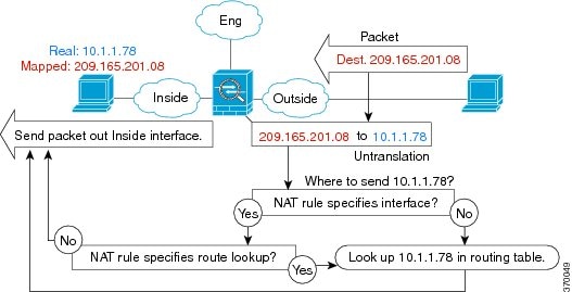
Figure 3-16 Routed Mode Egress Interface Selection

NAT for VPN

NAT and Remote Access VPN

Figure 3-17 shows both an inside server (10.1.1.6) and a VPN client (209.165.201.10) accessing the Internet. Unless you configure split tunnelling for the VPN client (where only specified traffic goes through the VPN tunnel), then Internet-bound VPN traffic must also go through the ASA. When the VPN traffic enters the ASA, the ASA decrypts the packet; the resulting packet includes the VPN client local address (10.3.3.10) as the source. For both inside and VPN client local networks, you need a public IP address provided by NAT to access the Internet. The below example uses interface PAT rules. To allow the VPN traffic to exit the same interface it entered, you also need to enable intra-interface communication (AKA “hairpin” networking).
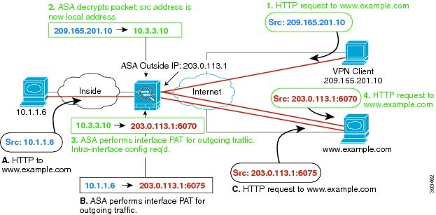
Figure 3-17 Interface PAT for Internet-Bound VPN Traffic (Intra-Interface)

Figure 3-18 shows a VPN client that wants to access an inside mail server. Because the ASA expects traffic between the inside network and any outside network to match the interface PAT rule you set up for Internet access, traffic from the VPN client (10.3.3.10) to the SMTP server (10.1.1.6) will be dropped due to a reverse path failure: traffic from 10.3.3.10 to 10.1.1.6 does not match a NAT rule, but returning traffic from 10.1.1.6 to 10.3.3.10 should match the interface PAT rule for outgoing traffic. Because forward and reverse flows do not match, the ASA drops the packet when it is received. To avoid this failure, you need to exempt the inside-to-VPN client traffic from the interface PAT rule by using an identity NAT rule between those networks. Identity NAT simply translates an address to the same address.
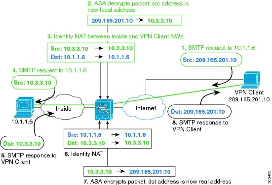
Figure 3-18 Identity NAT for VPN Clients

See the following sample NAT configuration for the above network:
! Enable hairpin for non-split-tunneled VPN client traffic:
same-security-traffic permit intra-interface
 
! Identify local VPN network, & perform object interface PAT when going to Internet:
object network vpn_local
subnet 10.3.3.0 255.255.255.0
nat (outside,outside) dynamic interface
 
! Identify inside network, & perform object interface PAT when going to Internet:
object network inside_nw
subnet 10.1.1.0 255.255.255.0
nat (inside,outside) dynamic interface
 
! Use twice NAT to pass traffic between the inside network and the VPN client without
! address translation (identity NAT):
nat (inside,outside) source static inside_nw inside_nw destination static vpn_local vpn_local

NAT and Site-to-Site VPN

Figure 3-19 shows a site-to-site tunnel connecting the Boulder and San Jose offices. For traffic that you want to go to the Internet (for example from 10.1.1.6 in Boulder to www.example.com), you need a public IP address provided by NAT to access the Internet. The below example uses interface PAT rules. However, for traffic that you want to go over the VPN tunnel (for example from 10.1.1.6 in Boulder to 10.2.2.78 in San Jose), you do not want to perform NAT; you need to exempt that traffic by creating an identity NAT rule. Identity NAT simply translates an address to the same address.
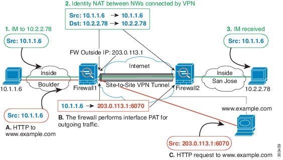
Figure 3-19 Interface PAT and Identity NAT for Site-to-Site VPN

Figure 3-20 shows a VPN client connected to ASA1 (Boulder), with a Telnet request for a server (10.2.2.78) accessible over a site-to-site tunnel between ASA1 and ASA2 (San Jose). Because this is a hairpin connection, you need to enable intra-interface communication, which is also required for non-split-tunneled Internet-bound traffic from the VPN client. You also need to configure identity NAT between the VPN client and the Boulder & San Jose networks, just as you would between any networks connected by VPN to exempt this traffic from outbound NAT rules.
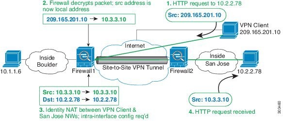
Figure 3-20 VPN Client Access to Site-to-Site VPN

See the following sample NAT configuration for ASA1 (Boulder):
! Enable hairpin for VPN client traffic:
same-security-traffic permit intra-interface
 
! Identify local VPN network, & perform object interface PAT when going to Internet:
object network vpn_local
subnet 10.3.3.0 255.255.255.0
nat (outside,outside) dynamic interface
 
! Identify inside Boulder network, & perform object interface PAT when going to Internet:
object network boulder_inside
subnet 10.1.1.0 255.255.255.0
nat (inside,outside) dynamic interface
 
! Identify inside San Jose network for use in twice NAT rule:
object network sanjose_inside
subnet 10.2.2.0 255.255.255.0
 
! Use twice NAT to pass traffic between the Boulder network and the VPN client without
! address translation (identity NAT):
nat (inside,outside) source static boulder_inside boulder_inside destination static vpn_local vpn_local
 
! Use twice NAT to pass traffic between the Boulder network and San Jose without
! address translation (identity NAT):
nat (inside,outside) source static boulder_inside boulder_inside destination static sanjose_inside sanjose_inside
 
! Use twice NAT to pass traffic between the VPN client and San Jose without
! address translation (identity NAT):
nat (outside,outside) source static vpn_local vpn_local destination static sanjose_inside sanjose_inside
 
See the following sample NAT configuration for ASA2 (San Jose):
! Identify inside San Jose network, & perform object interface PAT when going to Internet:
object network sanjose_inside
subnet 10.2.2.0 255.255.255.0
nat (inside,outside) dynamic interface
 
! Identify inside Boulder network for use in twice NAT rule:
object network boulder_inside
subnet 10.1.1.0 255.255.255.0
 
! Identify local VPN network for use in twice NAT rule:
object network vpn_local
subnet 10.3.3.0 255.255.255.0
 
! Use twice NAT to pass traffic between the San Jose network and Boulder without
! address translation (identity NAT):
nat (inside,outside) source static sanjose_inside sanjose_inside destination static boulder_inside boulder_inside
 
! Use twice NAT to pass traffic between the San Jose network and the VPN client without
! address translation (identity NAT):
nat (inside,outside) source static sanjose_inside sanjose_inside destination static vpn_local vpn_local
 

NAT and VPN Management Access

When using VPN, you can allow management access to an interface other than the one from which you entered the ASA (see the management-access command). For example, if you enter the ASA from the outside interface, the management-access feature lets you connect to the inside interface using ASDM, SSH, Telnet, or SNMP; or you can ping the inside interface.
Figure 3-21 shows a VPN client Telnetting to the ASA inside interface. When you use a management-access interface, and you configure identity NAT according to the “NAT and Remote Access VPN” or “NAT and Site-to-Site VPN” section, you must configure NAT with the route lookup option. Without route lookup, the ASA sends traffic out the interface specified in the NAT command, regardless of what the routing table says; in the below example, the egress interface is the inside interface. You do not want the ASA to send the management traffic out to the inside network; it will never return to the inside interface IP address. The route lookup option lets the ASA send the traffic directly to the inside interface IP address instead of to the inside network. For traffic from the VPN client to a host on the inside network, the route lookup option will still result in the correct egress interface (inside), so normal traffic flow is not affected. See the “Determining the Egress Interface” section for more information about the route lookup option.
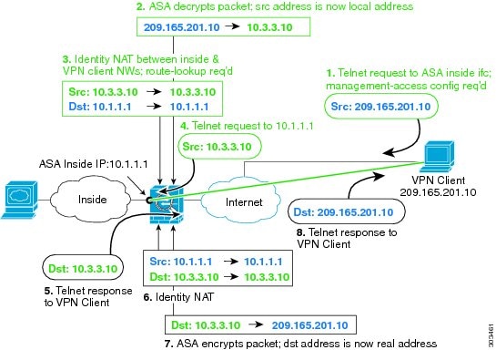
Figure 3-21 VPN Management Access

See the following sample NAT configuration for the above network:
! Enable hairpin for non-split-tunneled VPN client traffic:
same-security-traffic permit intra-interface
 
! Enable management access on inside ifc:
management-access inside
 
! Identify local VPN network, & perform object interface PAT when going to Internet:
object network vpn_local
subnet 10.3.3.0 255.255.255.0
nat (outside,outside) dynamic interface
 
! Identify inside network, & perform object interface PAT when going to Internet:
object network inside_nw
subnet 10.1.1.0 255.255.255.0
nat (inside,outside) dynamic interface
 
! Use twice NAT to pass traffic between the inside network and the VPN client without
! address translation (identity NAT), w/route-lookup:
nat (outside,inside) source static vpn_local vpn_local destination static inside_nw inside_nw route-lookup
 

Troubleshooting NAT and VPN

See the following monitoring tools for troubleshooting NAT issues with VPN:
  • Packet tracer—When used correctly, a packet tracer shows which NAT rules a packet is hitting.
  • show nat detail —Shows hit counts and untranslated traffic for a given NAT rule.
  • show conn all —Lets you see active connections including to and from the box traffic.
To familiarize yourself with a non-working configuration vs. a working configuration, you can perform the following steps:
1. Configure VPN without identity NAT.
2. Enter show nat detail and show conn all .
3. Add the identity NAT configuration.
  • Repeat show nat detail and show conn all .

DNS and NAT

You might need to configure the ASA to modify DNS replies by replacing the address in the reply with an address that matches the NAT configuration. You can configure DNS modification when you configure each translation rule.
This feature rewrites the address in DNS queries and replies that match a NAT rule (for example, the A record for IPv4, the AAAA record for IPv6, or the PTR record for reverse DNS queries). For DNS replies traversing from a mapped interface to any other interface, the record is rewritten from the mapped value to the real value. Inversely, for DNS replies traversing from any interface to a mapped interface, the record is rewritten from the real value to the mapped value.

NoteDNS rewrite is not applicable for PAT because multiple PAT rules are applicable for each A-record, and the PAT rule to use is ambiguous.


NoteIf you configure a twice NAT rule, you cannot configure DNS modification if you specify the source address as well as the destination address. These kinds of rules can potentially have a different translation for a single address when going to A vs. B. Therefore, the ASA cannot accurately match the IP address inside the DNS reply to the correct twice NAT rule; the DNS reply does not contain information about which source/destination address combination was in the packet that prompted the DNS request.


NoteThis feature requires DNS application inspection to be enabled, which it is by default. See the“DNS Inspection” section for more information.

Figure 3-22 shows a DNS server that is accessible from the outside interface. A server, ftp.cisco.com, is on the inside interface. You configure the ASA to statically translate the ftp.cisco.com real address (10.1.3.14) to a mapped address (209.165.201.10) that is visible on the outside network. In this case, you want to enable DNS reply modification on this static rule so that inside users who have access to ftp.cisco.com using the real address receive the real address from the DNS server, and not the mapped address. When an inside host sends a DNS request for the address of ftp.cisco.com, the DNS server replies with the mapped address (209.165.201.10). The ASA refers to the static rule for the inside server and translates the address inside the DNS reply to 10.1.3.14. If you do not enable DNS reply modification, then the inside host attempts to send traffic to 209.165.201.10 instead of accessing ftp.cisco.com directly.
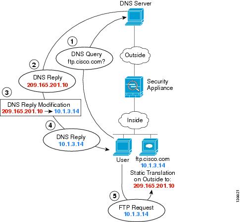
Figure 3-22 DNS Reply Modification, DNS Server on Outside

Figure 3-23 shows a user on the inside network requesting the IP address for ftp.cisco.com, which is on the DMZ network, from an outside DNS server. The DNS server replies with the mapped address (209.165.201.10) according to the static rule between outside and DMZ even though the user is not on the DMZ network. The ASA translates the address inside the DNS reply to 10.1.3.14. If the user needs to access ftp.cisco.com using the real address, then no further configuration is required. If there is also a static rule between the inside and DMZ, then you also need to enable DNS reply modification on this rule. The DNS reply will then be modified two times.In this case, the ASA again translates the address inside the DNS reply to 192.168.1.10 according to the static rule between inside and DMZ.
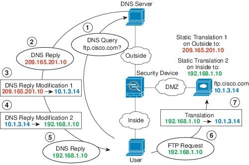
Figure 3-23 DNS Reply Modification, DNS Server, Host, and Server on Separate Networks

Figure 3-24 shows an FTP server and DNS server on the outside. The ASA has a static translation for the outside server. In this case, when an inside user requests the address for ftp.cisco.com from the DNS server, the DNS server responds with the real address, 209.165.20.10. Because you want inside users to use the mapped address for ftp.cisco.com (10.1.2.56) you need to configure DNS reply modification for the static translation.
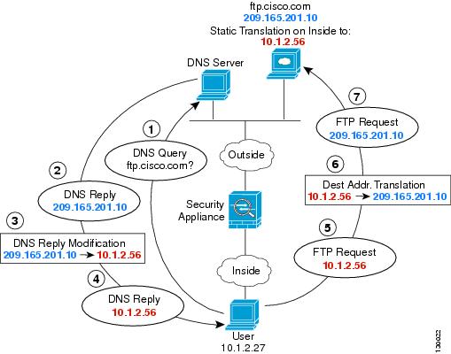
Figure 3-24 DNS Reply Modification, DNS Server on Host Network

Figure 3-24 shows an FTP server and DNS server on the outside IPv4 network. The ASA has a static translation for the outside server. In this case, when an inside IPv6 user requests the address for ftp.cisco.com from the DNS server, the DNS server responds with the real address, 209.165.200.225. Because you want inside users to use the mapped address for ftp.cisco.com (2001:DB8::D1A5:C8E1) you need to configure DNS reply modification for the static translation. This example also includes a static NAT translation for the DNS server, and a PAT rule for the inside IPv6 hosts.
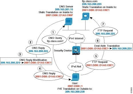
Figure 3-25 DNS64 Reply Modification Using Outside NAT

Figure 3-26 shows an FTP server and DNS server on the outside. The ASA has a static translation for the outside server. In this case, when an inside user performs a reverse DNS lookup for 10.1.2.56, the ASA modifies the reverse DNS query with the real address, and the DNS server responds with the server name, ftp.cisco.com.
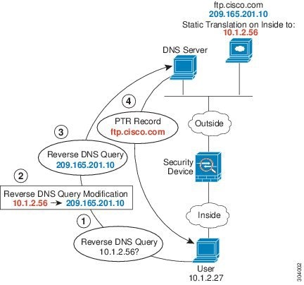
Figure 3-26 PTR Modification, DNS Server on Host Network

среда, 8 февраля 2017 г.

Configuring and Verifying the BGP Conditional Advertisement Feature

Background Theory

Normally, routes are propagated regardless of the existence of a different path. The BGP conditional advertisement feature uses the non-exist-map and the advertise-map keywords of the neighbor advertise-map command in order to track routes by the route prefix. If a route prefix is not present in output of the non-exist-map command, then the route specified by the advertise-map command is announced. This feature is useful for multihomed networks, in which some prefixes are advertised to one of the providers only if information from the other provider is not present (this indicates a failure in the peering session or partial reachability).
The conditional BGP announcements are sent in addition to the normal announcements that a BGP router sends to its peers.

Network Diagram

This document uses the network setup shown in this diagram.
Here, the loopback interface of R103 is used to announce 192.168.50.0/24 to R102. R102 has a BGP network, 128.16.16.0/24, which is announced to both its external BGP (eBGP) peers, R101 and R103, by default.
cond_adv_01.gif
With the BGP conditional advertisement feature, you can now accomplish these tasks on R102:
  • If 192.168.50.0/24 exists in R102's BGP table, then do not advertise the 128.16.16.0/24 network to R101.
  • If 192.168.50.0/24 does not exist in R102's BGP table, then advertise the 128.16.16.0/24 network to R101.
With Cisco IOS® 12.2T or later versions, the exist-map keyword can be used to accomplish these tasks as well:
  • If 192.168.50.0/24 exists in R102's BGP table, then advertise the 128.16.16.0/24 network to R101.
  • If 192.168.50.0/24 does not exist in R102's BGP table, then do not advertise the 128.16.16.0/24 network to R101.

R102
hostname R102 
! 
interface Loopback0 
 ip address 128.16.16.1 255.255.255.0 
! 
interface Serial8/0 
 ip address 10.10.10.2 255.255.255.0 
! 
interface Serial9/0 
 ip address 10.10.20.2 255.255.255.0 
! 
router bgp 2 
 bgp log-neighbor-changes 
 network 128.16.16.0 mask 255.255.255.0 
 network 130.130.0.0 
 neighbor 10.10.10.1 remote-as 1 
 neighbor 10.10.10.1 advertise-map ADVERTISE non-exist-map NON-EXIST

!--- Advertises the routes matched in the route-map ADVERTISE (128.16.16.0/24) !--- only if the routes matched in route-map NON-EXIST (192.168.50.0/24) !--- do not exist in the BGP table.
 
 neighbor 10.10.20.3 remote-as 3 
! 
ip route 130.130.0.0 255.255.0.0 Null0 
! 
access-list 60 permit 128.16.16.0 0.0.0.255 
access-list 65 permit 192.168.50.0 0.0.0.255 
! 
route-map NON-EXIST permit 10 
 match ip address 65 
!  
route-map ADVERTISE permit 10 
 match ip address 60 
!

Verify the Configuration

Example 1

This example verifies what BGP looks like when 192.168.50.0/24 is in R102's BGP table:
cond_adv_01.gif
First check to see if 192.168.50.0/24 exists in R102's BGP table:
R102# 
show ip bgp

BGP table version is 6, local router ID is 128.16.16.1
Status codes: s suppressed, d damped, h history, * valid, > best, i - internal
Origin codes: i - IGP, e - EGP, ? - incomplete

   Network          Next Hop            Metric LocPrf Weight Path
*> 128.16.16.0/24   0.0.0.0                  0         32768 i
*> 130.130.0.0      0.0.0.0                  0         32768 i
*> 192.168.50.0     10.10.20.3               0             0 3 i
*> 200.200.200.0    10.10.10.1               0             0 1 i
Since 192.168.50.0/24 is in R102's BGP table, then R102 must not advertise 128.16.16/24 to R101.
R102# show ip bgp neighbors 10.10.10.1 advertised-routes 
BGP table version is 6, local router ID is 128.16.16.1
Status codes: s suppressed, d damped, h history, * valid, > best, i - internal
Origin codes: i - IGP, e - EGP, ? - incomplete

   Network          Next Hop            Metric LocPrf Weight Path
*> 130.130.0.0      0.0.0.0                  0         32768 i
*> 192.168.50.0     10.10.20.3               0             0 3 i

!--- Note 128.16.16.0/24 is not advertised to neighbor 10.10.10.1.


R102# show ip bgp 128.16.16.0
BGP routing table entry for 128.16.16.0/24, version 6
Paths: (1 available, best #1, table Default-IP-Routing-Table)
  Advertised to non peer-group peers:

!--- This is not advertised to R101.
  
10.10.20.3     
  Local
    0.0.0.0 from 0.0.0.0 (128.16.16.1)
      Origin IGP, metric 0, localpref 100, weight 32768, valid, sourced, local, best

Then check the status of the conditional advertisement on R102:
R102# show ip bgp neighbors 10.10.10.1
BGP neighbor is 10.10.10.1,  remote AS 1, external link
  BGP version 4, remote router ID 200.200.200.1
  BGP state = Established, up for 02:27:07
  Last read 00:00:07, hold time is 180, keepalive interval is 60 seconds

 
!--- Output suppressed. 


 For address family: IPv4 Unicast
  BGP table version 6, neighbor version 6
  Index 1, Offset 0, Mask 0x2
  Condition-map NON-EXIST, Advertise-map ADVERTISE, status: Withdraw
  1 accepted prefixes consume 36 bytes
  Prefix advertised 3, suppressed 0, withdrawn 1
  Number of NLRIs in the update sent: max 1, min 0


!--- Output suppressed. 


The output shows that the conditional advertisement is "withdrawn" and that the networks that match the route-map "ADVERTISE" are not announced to the peer 10.10.10.1.
In order to confirm the routes that match the route-map "ADVERTISE" are not announced to R101, check the BGP table on R101:
R101# show ip bgp 128.16.16.0
% Network not in table

Example 2

This example shows what BGP looks like when network 192.168.50.0/24 does not exist in the R102 BGP table:
cond_adv_02.gif
First, shut down the loopback interface 0 on R103 so that R103 no longer announces 192.168.50.0/24 to R102.
R103(config)# interface loopback 0
R103(config-if)# shutdown 
R103(config-if)#
03:29:36: %LINK-5-CHANGED: Interface Loopback0, changed state to administratively down

Then verify that R102 is not learning 192.168.50.0/24 and that the network is not included in the R102 BGP table.
R102# show ip bgp 
BGP table version is 8, local router ID is 128.16.16.1
Status codes: s suppressed, d damped, h history, * valid, > best, i - internal
Origin codes: i - IGP, e - EGP, ? - incomplete

   Network          Next Hop            Metric LocPrf Weight Path
*> 128.16.16.0/24   0.0.0.0                  0         32768 i
*> 130.130.0.0      0.0.0.0                  0         32768 i
*> 200.200.200.0    10.10.10.1               0             0 1 i

!--- Note 192.168.50.0/24 is not present.


Now, see how long it takes for the conditional advertisement kick in:
R102# 
debug ip bgp updates

*Mar  1 02:39:18.059: BGP(0): 10.10.20.3 rcv UPDATE about 192.168.50.0/24
-- withdrawn
*Mar  1 02:39:18.059: BGP(0): no valid path for 192.168.50.0/24
*Mar  1 02:39:18.079: BGP(0): nettable_walker 192.168.50.0/24 no best path
*Mar  1 02:39:18.219: BGP(0): 10.10.10.1 computing updates, afi 0, neighbor 
version 10, table version 11, starting at 0.0.0.0
*Mar  1 02:39:18.219: BGP(0): 10.10.10.1 send unreachable 192.168.50.0/24
*Mar  1 02:39:18.219: BGP(0): 10.10.10.1 send UPDATE 192.168.50.0/24 
-- unreachable
*Mar  1 02:39:18.219: BGP(0): 10.10.10.1 1 updates enqueued (average=27, maximum=27)
*Mar  1 02:39:18.219: BGP(0): 10.10.10.1 update run completed, afi 0, ran for 0ms, 
neighbor version 10, start version 11, throttled to 11

*Mar  1 02:40:04.747: BPG(0): Condition NON-EXIST changes to Advertise
*Mar  1 02:40:04.747: BGP(0): net 128.16.16.0/24 matches ADV MAP ADVERTISE: 
bump version to 12
*Mar  1 02:40:05.187: BGP(0): nettable_walker 128.16.16.0/24 route sourced 
locally
*Mar  1 02:40:05.187: BGP(0): 10.10.10.1 computing updates, afi 0, neighbor 
version 11, table version 12, starting at 0.0.0.0
*Mar  1 02:40:05.187: BGP(0): 10.10.10.1 128.16.16.0/24 matches advertise map 
ADVERTISE, state: Advertise
*Mar  1 02:40:05.187: BGP(0): 10.10.10.1 send UPDATE (format) 128.16.16.0/24, 
next 10.10.10.2, metric 0, path 
*Mar  1 02:40:05.187: BGP(0): 10.10.10.1 1 updates enqueued (average=52, maximum=52)
*Mar  1 02:40:05.187: BGP(0): 10.10.10.1 update run completed, afi 0, ran for 0ms, 
neighbor version 11, start version 12, throttled to 12

The conditional advertisement process is triggered by the BGP scanner process, which runs every 60 seconds. This means that the maximum time for the conditional advertisement to take effect is 60 seconds. The conditional advertisement can take effect sooner, depending on when the tracked route is removed from the BGP table and when the next instance of the BGP scanner occurs. Issue these commands on R102 in order to verify the conditional advertisement state on R102 for the neighbor 10.10.10.1:
R102# show ip bgp neighbors 10.10.10.1
BGP neighbor is 10.10.10.1,  remote AS 1, external link
  BGP version 4, remote router ID 200.200.200.1
  BGP state = Established, up for 02:45:27
  Last read 00:00:27, hold time is 180, keepalive interval is 60 seconds
  
!--- Output suppressed. 


 For address family: IPv4 Unicast
  BGP table version 12, neighbor version 12
  Index 1, Offset 0, Mask 0x2
  Condition-map NON-EXIST, Advertise-map ADVERTISE, status: Advertise
  1 accepted prefixes consume 36 bytes
  Prefix advertised 6, suppressed 0, withdrawn 4
  Number of NLRIs in the update sent: max 1, min 0
 
!--- Output suppressed. 


R101's BGP table and routing table has 128.16.16.0/24, as shown here:
Note: In this sample output, the conditional BGP announcements (network 128.16.16.0/24) are sent, in addition to the normal BGP announcements (network 130.130.0.0/16) that a BGP router sends to its peers.
R101# show ip bgp
BGP table version is 18, local router ID is 200.200.200.1
Status codes: s suppressed, d damped, h history, * valid, > best, i - internal
Origin codes: i - IGP, e - EGP, ? - incomplete

   Network          Next Hop            Metric LocPrf Weight Path
*> 128.16.16.0/24   10.10.10.2               0             0 2 i
*> 130.130.0.0      10.10.10.2               0             0 2 i
*> 200.200.200.0    0.0.0.0                  0         32768 i

R101# show ip route bgp
     128.16.0.0/24 is subnetted, 1 subnets
B       128.16.16.0 [20/0] via 10.10.10.2, 00:09:32
B    130.130.0.0/16 [20/0] via 10.10.10.2, 02:48:46

Example 3

This example involves the reinstallation of the 192.168.50.0/24 network in R102 in order to see how BGP changes from "Advertise" to "Withdraw."
cond_adv_01.gif
In order to reinstall 192.168.50.0/24, issue the no shutdown command to bring the interface loopback 0 on R103 to "UP".
R103(config)# interface loopback 0
R103(config-if)# no shutdown
R103(config-if)#
03:49:06: %LINK-3-UPDOWN: Interface Loopback0, 
changed state to up
03:49:07: %LINEPROTO-5-UPDOWN: Line protocol on 
Interface Loopback0, changed state to up

!--- R102 kicks in conditional advertisement the moment the !--- conditional network is received again.

*Mar  1 02:51:42.227: BGP(0): 10.10.20.3 rcvd UPDATE w/ attr: 
nexthop 10.10.20.3, origin i, metric 0, path 3
*Mar  1 02:51:42.227: BGP(0): 10.10.20.3 rcvd 192.168.50.0/24
*Mar  1 02:51:42.247: BGP(0): Revise route installing 192.168.50.0/24 -> 
10.10.20.3 to main IP table
*Mar  1 02:51:42.379: BGP(0): 10.10.10.1 computing updates, afi 0, 
neighbor version 12, table version 13, starting at 0.0.0.0
*Mar  1 02:51:42.379: BGP(0): 10.10.10.1 send UPDATE (format) 
192.168.50.0/24, next 10.10.10.2, metric 0, path 3
*Mar  1 02:51:42.379: BGP(0): 10.10.10.1 1 updates enqueued 
(average=47, maximum=47)
*Mar  1 02:51:42.379: BGP(0): 10.10.10.1 update run completed, afi 0, 
ran for 0ms, neighbor version 12, start version 13, throttled to 13

*Mar  1 02:52:09.159: BPG(0): Condition NON-EXIST changes to Withdraw
*Mar  1 02:52:09.159: BGP(0): net 128.16.16.0/24 matches ADV MAP 
ADVERTISE: bump version to 14
*Mar  1 02:52:09.499: BGP(0): nettable_walker 128.16.16.0/24 route 
sourced locally
*Mar  1 02:52:11.559: BGP(0): 10.10.10.1 computing updates, afi 0, 
neighbor version 13, table version 14, starting at 0.0.0.0
*Mar  1 02:52:11.559: BGP(0): 10.10.10.1 128.16.16.0/24 matches advertise 
map ADVERTISE, state: Withdraw
*Mar  1 02:52:11.559: BGP(0): 10.10.10.1 send unreachable 128.16.16.0/24
*Mar  1 02:52:11.559: BGP(0): 10.10.10.1 send UPDATE 128.16.16.0/24 -- unreachable
*Mar  1 02:52:11.559: BGP(0): 10.10.10.1 1 updates enqueued (average=27, maximum=27)
*Mar  1 02:52:11.559: BGP(0): 10.10.10.1 update run completed, afi 0, ran for 0ms, 
neighbor version 13, start version 14, throttled to 14

R102 no longer advertises 128.16.16.0/24 to R101.
R102# show ip bgp neighbors 10.10.10.1 advertised-routes 
BGP table version is 14, local router ID is 128.16.16.1
Status codes: s suppressed, d damped, h history, * valid, > best, i - internal
Origin codes: i - IGP, e - EGP, ? - incomplete

   Network          Next Hop            Metric LocPrf Weight Path
*> 130.130.0.0      0.0.0.0                  0         32768 i
*> 192.168.50.0     10.10.20.3               0             0 3 i

!--- Note 128.16.16.0/24 is not advertised.

R102# show ip bgp neighbors 10.10.10.1
BGP neighbor is 10.10.10.1,  remote AS 1, external link
  BGP version 4, remote router ID 200.200.200.1
  BGP state = Established, up for 03:01:32
  Last read 00:00:31, hold time is 180, keepalive interval is 60 seconds
  Neighbor capabilities:
!--- Output supressed.

 For address family: IPv4 Unicast
  BGP table version 14, neighbor version 14
  Index 1, Offset 0, Mask 0x2
  Condition-map NON-EXIST, Advertise-map ADVERTISE, status: Withdraw
  1 accepted prefixes consume 36 bytes
  Prefix advertised 7, suppressed 0, withdrawn 5
  Number of NLRIs in the update sent: max 1, min 0
  
!--- Output supressed.


Note: In a real world scenario, AS1 and AS3 are connected to the Internet (Global BGP). Hence the network 192.168.50.0/24 could be propagated through a global bgp mesh from AS3 to the AS1 (R101) BGP table. AS1, in turn, could propagate the prefix 192.168.50.0 to R102 (depending on the policy agreement between AS1 and AS2). If R101 propagates AS3 routes learned from the global BGP mesh to R102, then the conditional advertisement can fail if additional checks are not placed in the non-exist map.
In order to better understand why conditional advertisement fails, consider this scenario. AS1 learns 192.168.50.0/24 from the global bgp mesh and announces 192.168.50.0/24 to AS2 (R102). R102 also learns the prefix 192.168.50.0/24 from its direct peering to R103 (over the R102 to R103 link). When the direct link between R102 and R103 fails, you expect that the prefix 192.168.50.0/24 ceases to exist in R102's BGP table and the conditional advertisement kicks in and announces prefix 128.16.16.0/24 to R101. However, since the prefix 192.168.50.0/24 continues to exist in the R102 BGP table (learned from R101), the conditional advertisement breaks because the prefix in the non-exist map still exists in the R102 BGP table. To ensure that the prefix 192.168.50.0/24 is learned only from the direct connection to AS3 (R102 to R103) in order for conditional advertisement to kick in, add a match as_path statement under the non-exist map that matches the AS_PATH of prefix 192.168.50.0/24 learned from direct connection (which in this case is AS 3). The regular expression for this case is ^3. For more information on regular expressions, refer to Using Regular Expressions in BGP. Beware that you cannot match just the as-path, and not match the prefix. The match as-path can only supplement the matching criteria for the matched prefix. In other words, you cannot advertise some prefixes to a neighbor if no prefix exists from a certain AS #.
The new configuration on R102 is shown here. The additions are in bold.
R101
hostname R102  
!  
interface Loopback0  
 ip address 128.16.16.1 255.255.255.0  
!  
interface Serial8/0  
 ip address 10.10.10.2 255.255.255.0  
!  
interface Serial9/0  
 ip address 10.10.20.2 255.255.255.0  
!  
router bgp 2  
 bgp log-neighbor-changes  
 network 128.16.16.0 mask 255.255.255.0  
 network 130.130.0.0  
 neighbor 10.10.10.1 remote-as 1  
 neighbor 10.10.10.1 advertise-map ADVERTISE non-exist-map NON-EXIST  
 neighbor 10.10.20.3 remote-as 3  
!  
ip route 130.130.0.0 255.255.0.0 Null0 
! 
ip as-path access-list 1 permit ^3 
!  
access-list 60 permit 128.16.16.0 0.0.0.255  
access-list 65 permit 192.168.50.0 0.0.0.255  
!  
route-map NON-EXIST permit 10  
 match ip address 65  
  match as-path 1 
!  
route-map ADVERTISE permit 10  
 match ip address 60  
!

What are the different between distribute list, prefix-list and filter-list

The distribute-list and prefix-list perform route filtering based on IP network addresses and netmasks of routes being advertised. The distribute-list refers to an ACL to match the individual networks and netmasks, while prefix-list refers to a prefix list to do this matching. In fact, the use of distribute-list and prefix-list for a particular BGP neighbor in a particular direction (in or out) is mutually exclusive, because they both accomplish the very same goal, just using a different route selection/filtering mechanism (an ACL vs. a prefix list). It is generally better to use prefix lists instead of ACLs - they are much more cleaner and more comprehensible, optimized to match networks/netmasks and subnets thereof.
The filter-list performs route filtering based on the contents of the AS_PATH attribute - the sequence and values of atonomous system numbers. To do this, you would configure an as-path ACL that contains one or more regular expressions matching the particular sequence of ASNs in the AS_PATH attribute, and apply it to a neighbor and a particular direction with the filter-list command. With a filter-list, you do not perform route matching/filtering based on IP addresses and netmasks.