NAT Rule Order
Network object NAT rules and twice NAT rules are stored in a single table that is divided into three sections. Section 1 rules are applied first, then section 2, and finally section 3, until a match is found. For example, if a match is found in section 1, sections 2 and 3 are not evaluated. Table 3-1 shows the order of rules within each section.
Network object NAT rules and twice NAT rules are stored in a single table that is divided into three sections. Section 1 rules are applied first, then section 2, and finally section 3, until a match is found. For example, if a match is found in section 1, sections 2 and 3 are not evaluated. Table 3-1 shows the order of rules within each section.
NAT Interfaces
Mapped Addresses and Routing
When you translate the real address to a mapped address, the mapped address you choose determines how to configure routing, if necessary, for the mapped address.
See additional guidelines about mapped IP addresses in “Configuring Network Object NAT,” and Chapter5, “Configuring Twice NAT”
If you use addresses on the same network as the mapped interface, the ASA uses proxy ARP to answer any ARP requests for the mapped addresses, thus intercepting traffic destined for a mapped address. This solution simplifies routing because the ASA does not have to be the gateway for any additional networks. This solution is ideal if the outside network contains an adequate number of free addresses, a consideration if you are using a 1:1 translation like dynamic NAT or static NAT. Dynamic PAT greatly extends the number of translations you can use with a small number of addresses, so even if the available addresses on the outside network is small, this method can be used. For PAT, you can even use the IP address of the mapped interface.

Note If you configure the mapped interface to be any interface, and you specify a mapped address on the same network as one of the mapped interfaces, then if an ARP request for that mapped address comes in on a different interface, then you need to manually configure an ARP entry for that network on the ingress interface, specifying its MAC address (see the arp command). Typically, if you specify any interface for the mapped interface, then you use a unique network for the mapped addresses, so this situation would not occur.
If you need more addresses than are available on the mapped interface network, you can identify addresses on a different subnet. The upstream router needs a static route for the mapped addresses that points to the ASA. Alternatively for routed mode, you can configure a static route on the ASA for the mapped addresses, and then redistribute the route using your routing protocol. For transparent mode, if the real host is directly-connected, configure the static route on the upstream router to point to the ASA: specify the bridge group IP address. For remote hosts in transparent mode, in the static route on the upstream router, you can alternatively specify the downstream router IP address.
The default behavior for identity NAT has proxy ARP enabled, matching other static NAT rules. You can disable proxy ARP if desired. Note : You can also disable proxy ARP for regular static NAT if desired, in which case you need to be sure to have proper routes on the upstream router.
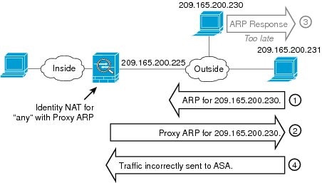
Normally for identity NAT, proxy ARP is not required, and in some cases can cause connectivity issues. For example, if you configure a broad identity NAT rule for “any” IP address, then leaving proxy ARP enabled can cause problems for hosts on the network directly-connected to the mapped interface. In this case, when a host on the mapped network wants to communicate with another host on the same network, then the address in the ARP request matches the NAT rule (which matches “any” address). The ASA will then proxy ARP for the address, even though the packet is not actually destined for the ASA. (Note that this problem occurs even if you have a twice NAT rule; although the NAT rule must match both the source and destination addresses, the proxy ARP decision is made only on the “source” address). If the ASA ARP response is received before the actual host ARP response, then traffic will be mistakenly sent to the ASA (see Figure 3-14).
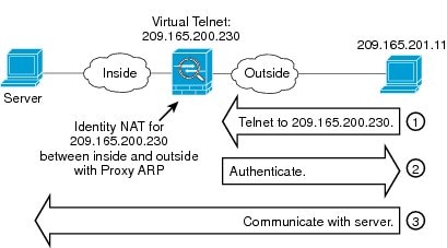
In rare cases, you need proxy ARP for identity NAT; for example for virtual Telnet. When using AAA for network access, a host needs to authenticate with the ASA using a service like Telnet before any other traffic can pass. You can configure a virtual Telnet server on the ASA to provide the necessary login. When accessing the virtual Telnet address from the outside, you must configure an identity NAT rule for the address specifically for the proxy ARP functionality. Due to internal processes for virtual Telnet, proxy ARP lets the ASA keep traffic destined for the virtual Telnet address rather than send the traffic out the source interface according to the NAT rule. (See Figure 3-15).
Transparent Mode Routing Requirements for Remote Networks
Determining the Egress Interface
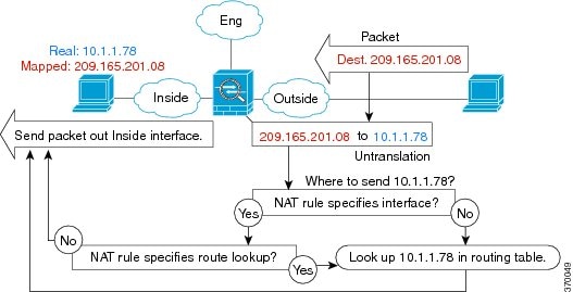
When the ASA receives traffic for a mapped address, the ASA unstranslates the destination address according to the NAT rule, and then it sends the packet on to the real address. The ASA determines the egress interface for the packet in the following ways:
- Transparent mode—The ASA determines the egress interface for the real address by using the NAT rule; you must specify the source and destination interfaces as part of the NAT rule.
- Routed mode—The ASA determines the egress interface in one of the following ways:
– You configure the interface in the NAT rule—The ASA uses the NAT rule to determine the egress interface. However, you have the option to always use a route lookup instead. In certain scenarios, a route lookup override is required; for example, see the “NAT and VPN Management Access” section.
– You do not configure the interface in the NAT rule—The ASA uses a route lookup to determine the egress interface.
Figure 3-16 shows the egress interface selection method in routed mode. In almost all cases, a route lookup is equivalent to the NAT rule interface, but in some configurations, the two methods might differ.
NAT for VPN
- NAT and Remote Access VPN
- NAT and Site-to-Site VPN
- NAT and VPN Management Access
- Troubleshooting NAT and VPN
NAT and Remote Access VPN
Figure 3-17 shows both an inside server (10.1.1.6) and a VPN client (209.165.201.10) accessing the Internet. Unless you configure split tunnelling for the VPN client (where only specified traffic goes through the VPN tunnel), then Internet-bound VPN traffic must also go through the ASA. When the VPN traffic enters the ASA, the ASA decrypts the packet; the resulting packet includes the VPN client local address (10.3.3.10) as the source. For both inside and VPN client local networks, you need a public IP address provided by NAT to access the Internet. The below example uses interface PAT rules. To allow the VPN traffic to exit the same interface it entered, you also need to enable intra-interface communication (AKA “hairpin” networking).
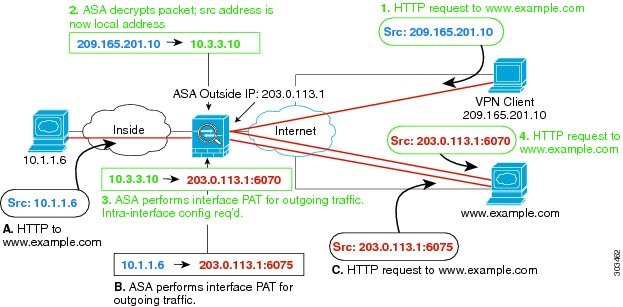
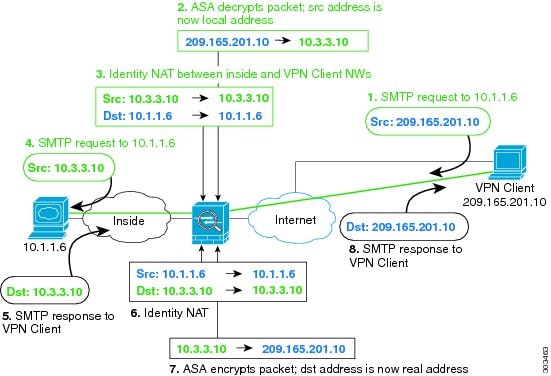
Figure 3-18 shows a VPN client that wants to access an inside mail server. Because the ASA expects traffic between the inside network and any outside network to match the interface PAT rule you set up for Internet access, traffic from the VPN client (10.3.3.10) to the SMTP server (10.1.1.6) will be dropped due to a reverse path failure: traffic from 10.3.3.10 to 10.1.1.6 does not match a NAT rule, but returning traffic from 10.1.1.6 to 10.3.3.10 should match the interface PAT rule for outgoing traffic. Because forward and reverse flows do not match, the ASA drops the packet when it is received. To avoid this failure, you need to exempt the inside-to-VPN client traffic from the interface PAT rule by using an identity NAT rule between those networks. Identity NAT simply translates an address to the same address.
NAT and Site-to-Site VPN
Figure 3-19 shows a site-to-site tunnel connecting the Boulder and San Jose offices. For traffic that you want to go to the Internet (for example from 10.1.1.6 in Boulder to www.example.com), you need a public IP address provided by NAT to access the Internet. The below example uses interface PAT rules. However, for traffic that you want to go over the VPN tunnel (for example from 10.1.1.6 in Boulder to 10.2.2.78 in San Jose), you do not want to perform NAT; you need to exempt that traffic by creating an identity NAT rule. Identity NAT simply translates an address to the same address.
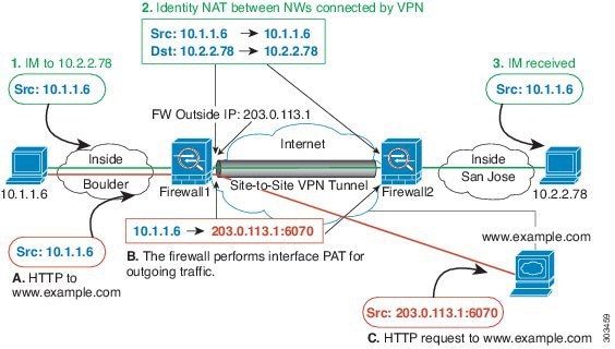
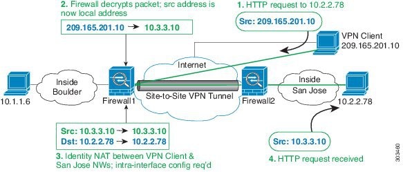
Figure 3-20 shows a VPN client connected to ASA1 (Boulder), with a Telnet request for a server (10.2.2.78) accessible over a site-to-site tunnel between ASA1 and ASA2 (San Jose). Because this is a hairpin connection, you need to enable intra-interface communication, which is also required for non-split-tunneled Internet-bound traffic from the VPN client. You also need to configure identity NAT between the VPN client and the Boulder & San Jose networks, just as you would between any networks connected by VPN to exempt this traffic from outbound NAT rules.
NAT and VPN Management Access
When using VPN, you can allow management access to an interface other than the one from which you entered the ASA (see the management-access command). For example, if you enter the ASA from the outside interface, the management-access feature lets you connect to the inside interface using ASDM, SSH, Telnet, or SNMP; or you can ping the inside interface.
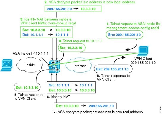
Figure 3-21 shows a VPN client Telnetting to the ASA inside interface. When you use a management-access interface, and you configure identity NAT according to the “NAT and Remote Access VPN” or “NAT and Site-to-Site VPN” section, you must configure NAT with the route lookup option. Without route lookup, the ASA sends traffic out the interface specified in the NAT command, regardless of what the routing table says; in the below example, the egress interface is the inside interface. You do not want the ASA to send the management traffic out to the inside network; it will never return to the inside interface IP address. The route lookup option lets the ASA send the traffic directly to the inside interface IP address instead of to the inside network. For traffic from the VPN client to a host on the inside network, the route lookup option will still result in the correct egress interface (inside), so normal traffic flow is not affected. See the “Determining the Egress Interface” section for more information about the route lookup option.
Troubleshooting NAT and VPN
DNS and NAT
You might need to configure the ASA to modify DNS replies by replacing the address in the reply with an address that matches the NAT configuration. You can configure DNS modification when you configure each translation rule.
This feature rewrites the address in DNS queries and replies that match a NAT rule (for example, the A record for IPv4, the AAAA record for IPv6, or the PTR record for reverse DNS queries). For DNS replies traversing from a mapped interface to any other interface, the record is rewritten from the mapped value to the real value. Inversely, for DNS replies traversing from any interface to a mapped interface, the record is rewritten from the real value to the mapped value.

Note DNS rewrite is not applicable for PAT because multiple PAT rules are applicable for each A-record, and the PAT rule to use is ambiguous.

Note If you configure a twice NAT rule, you cannot configure DNS modification if you specify the source address as well as the destination address. These kinds of rules can potentially have a different translation for a single address when going to A vs. B. Therefore, the ASA cannot accurately match the IP address inside the DNS reply to the correct twice NAT rule; the DNS reply does not contain information about which source/destination address combination was in the packet that prompted the DNS request.

Note This feature requires DNS application inspection to be enabled, which it is by default. See the“DNS Inspection” section for more information.
Figure 3-22 shows a DNS server that is accessible from the outside interface. A server, ftp.cisco.com, is on the inside interface. You configure the ASA to statically translate the ftp.cisco.com real address (10.1.3.14) to a mapped address (209.165.201.10) that is visible on the outside network. In this case, you want to enable DNS reply modification on this static rule so that inside users who have access to ftp.cisco.com using the real address receive the real address from the DNS server, and not the mapped address. When an inside host sends a DNS request for the address of ftp.cisco.com, the DNS server replies with the mapped address (209.165.201.10). The ASA refers to the static rule for the inside server and translates the address inside the DNS reply to 10.1.3.14. If you do not enable DNS reply modification, then the inside host attempts to send traffic to 209.165.201.10 instead of accessing ftp.cisco.com directly.
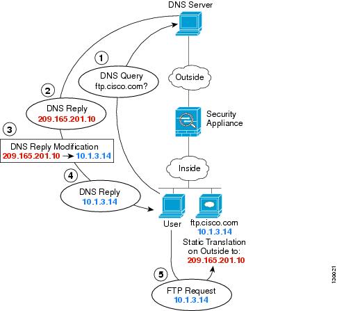
Figure 3-23 shows a user on the inside network requesting the IP address for ftp.cisco.com, which is on the DMZ network, from an outside DNS server. The DNS server replies with the mapped address (209.165.201.10) according to the static rule between outside and DMZ even though the user is not on the DMZ network. The ASA translates the address inside the DNS reply to 10.1.3.14. If the user needs to access ftp.cisco.com using the real address, then no further configuration is required. If there is also a static rule between the inside and DMZ, then you also need to enable DNS reply modification on this rule. The DNS reply will then be modified two times.In this case, the ASA again translates the address inside the DNS reply to 192.168.1.10 according to the static rule between inside and DMZ.
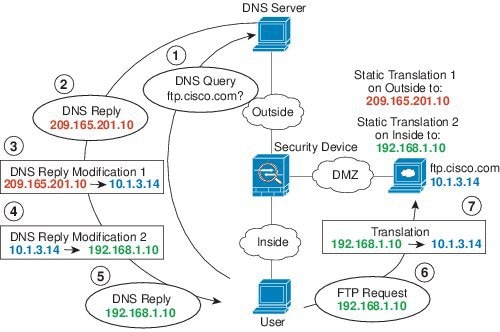
Figure 3-24 shows an FTP server and DNS server on the outside. The ASA has a static translation for the outside server. In this case, when an inside user requests the address for ftp.cisco.com from the DNS server, the DNS server responds with the real address, 209.165.20.10. Because you want inside users to use the mapped address for ftp.cisco.com (10.1.2.56) you need to configure DNS reply modification for the static translation.
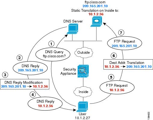
Figure 3-24 shows an FTP server and DNS server on the outside IPv4 network. The ASA has a static translation for the outside server. In this case, when an inside IPv6 user requests the address for ftp.cisco.com from the DNS server, the DNS server responds with the real address, 209.165.200.225. Because you want inside users to use the mapped address for ftp.cisco.com (2001:DB8::D1A5:C8E1) you need to configure DNS reply modification for the static translation. This example also includes a static NAT translation for the DNS server, and a PAT rule for the inside IPv6 hosts.
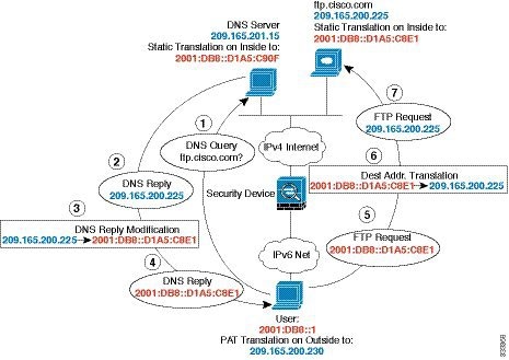
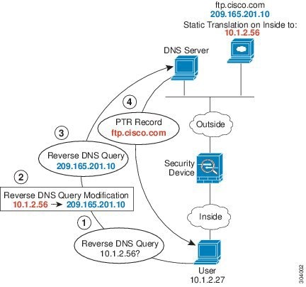
Figure 3-26 shows an FTP server and DNS server on the outside. The ASA has a static translation for the outside server. In this case, when an inside user performs a reverse DNS lookup for 10.1.2.56, the ASA modifies the reverse DNS query with the real address, and the DNS server responds with the server name, ftp.cisco.com.
Комментариев нет:
Отправить комментарий