Целью данной статьи является рассмотрение вопроса прохождения телефонного звонка через правила нормализации и маршруты. Также посмотрим на пример настроек Dial Plan, Voice Policy, Route на реальном примере.
Схема прохождения исходящего звонка
Общую схему прохождения звонка можно представить следующим образом:

Т.е получается что в примере пользователь набрал городской номер через 9-ку: 9-555-66-77, этот номер преобразовался в +78465556677, потом был найден маршрут для данного номера и номер был отправлен на шлюз (предварительно была выполнена трансляция согласно trunk configuration). И в итоге шлюз получил: 7(846)555-66-77
Настройка в интерфейсе Lync Server
Все настройки находятся в разделе Voice Routing:
Dial Plan: создание правил нормализации
Voice Policy: Голосовая политика, состоит из PSTN Usage в которую входят Route (маршруты).
Route: маршруты, входят в PSTN Usage
PSTN Usage: записи групп в которые входят маршруты, их можно использовать в разных политиках.
Trunk Configuration: трансляция номеров на выходе.
Основы регулярных выражений
Для создания шаблонов номеров в правилах нормализации, маршрутах используются регулярные выражения. При этом в нормализации необходимо для: какие номера и во что преобразовывать. В маршрутах: какие нормализованные номера отправлять на шлюз.
Разберем основные элементы регулярных выражений:
| Элемент выражения | Значение | Пример | Описание примера |
| ^ | Начало выражения | ^123 | Любое выражение начинается с ^ |
| $ | Конец выражения | ^(123)$ | Любое выражение заканчивается $ |
| \d | Определение количества цифр в выражении | ^(\d{8})$ | Если данному выражению подать на вход 96667788 то он будет преобразован в 96667788 |
| () | Определение группы. Все что стоит вне скобок – будет убираться. | ^9(\d{7})$ | Если данному выражению подать на вход 96667788 то он будет преобразован в 6667788 |
| [] | диапазон искомых цифр | ^[7-9](\d{7})$ | Если данному выражению подать на вход 76667788 или 86667788 или 96667788 то он будет преобразован в 6667788 |
| * | Задает 0 или большее кол-во цифр | ^(\d{7}\d*)$ | Под правило подпадают номера с количеством цифр 7 и более |
| + | Задает 1 или большее кол-во цифр | ^(\d{7}\d+)$ | Под правило подпадают номера с количеством цифр 8 и более |
| ? | Задает 0 или 1 цифру | ^(\d{7}\d?)$ | Под правило подпадают номера с количеством цифр 7 или 8 |
| {n} | Задает номер только из «n» цифр | ^(\d{8})$ | Под правило подпадают номера с количеством цифр 8 |
| {n,} | Задает номер только из «n» цифр и более | ^(\d{8,})$ | Под правило подпадают номера с количеством цифр 8 и более |
| {n,m} | Задает номер из «n» цифр до «m» включительно | ^(\d{8,12})$ | Под правило подпадают номера с количеством цифр от 8 до 12 |
| ?! | Кроме этого | ^(?![7,9])(\d{7})$ | Под правило подпадают номера с количеством цифр 7 кроме номеров, начинающихся с цифры 7 или 9 |
| | | Соответствие любому из условий перечисленных через знак | | ^(999$|112$) | Под правило подпадают номера 999 или 112 |
Пример настройки Dial Plan, Voice Policy, Route на реальном примере:
Вводные данные:
- Lync 2013
- Интеграция с телефонией через шлюз согласно схеме:

- Все абоненты получают уникальный внутренний номер в пределах организации(организация например в г.Самара). Внутренние номера, состоят из четырех знаков в формате XXXX. Номера абонентов PBX и Lync для удобства совпадают в трех последних символах и различаются только префиксом (первой цифрой):
1XXX – четырехзначный номер абонента PBX. (например 1555)
2ХХХ – четырехзначный номер абонента Lync. (например 2555)
- Префиксы для внешних вызовов(требования провайдера):
9-<номер 7 знаков> – местные вызовы;
9-<номер 2-3 знака> – выход на экстренные службы 112, 01, 02 (101,102) и т.д.;
9-8 — <код региона ><номер> – междугородние/мобильные.
9-8- 8482- <номер 6 знаков> – Местные вызовы в город Тольятти (выделим это направление для примера: допустим там филиал компании и связь только через pstn, или там находится большинство клиентов компании и т.д и т.п)
- Набор номеров абонентами производится согласно рисунку.
- Пользователи имеют ограничения на звонки по направлениям согласно политикам: Внутренние(включая экстренные), Внутренние+Самара, Внутренние+Самара+Тольятти, Внутренние + по России
Настройки Voice routing для нашей конфигурации:
Dial plan

Voice Policy:

Voice policy: Внутренние + по России

Route:

Под правила подпадают уже нормализованные (dial plan) номера:
^(\d{2,4})$ — под правило подпадают номера с количеством цифр от 2 до 4
^\+7846(\d{7})$ — под правило подпадают номера вида +7846 <+ 7 знаков>
^\+78482(\d{6})$ — под правило подпадают номера вида +78482 <+ 6 знаков>
^\+7(\d{10})$ — под правило подпадают номера вида +7 <+ 10 знаков>
Проверяем с помощью Test Voice Routing

Далее номера
необходимо транслировать согласно требованиям провайдера ( ранее в статье были указаны
префиксы для внешних вызовов). Это можно сделать с помощью Trunk Configuration:
необходимо транслировать согласно требованиям провайдера ( ранее в статье были указаны
префиксы для внешних вызовов). Это можно сделать с помощью Trunk Configuration:
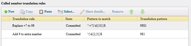
При этом:
Calling number translation rule – правила трансляции вызывающего номера
Called number translation rule – правила трансляции вызываемого номера
Defining the Associated SIP Trunk Configuration in the Lync Control Panel
Under the Voice Routing panel, click on the “Trunk Configuration” heading, and define a new Pool trunk. With a Pool trunk, you will be able to associate the trunk with the PSTN Gateway defined in your Topology that represents the SIP trunk.
The the New Trunk configuration dialog is show here:
In my experience, four settings that you want to pay particular attention to are:
- Encryption support level: this identifies what encryption (if any) will be made on the media traffic. They key is, you need to match whatever your peer SIP trunk is configured for. Note that encryption will use TLS which requires certificates.
- Refer support: in my experience, setting this option to “Enable sending refer to the gateway” will allow the caller-ID to be passed through to the SIP trunk and on to the called party.
- Centralized media processing: this indicates to Lync that the SIP trunk peer uses the same IP address for media as it does the SIP signaling. If you are having trouble getting Lync audio working, but the call is established, try enabling this if it is not already enabled.
- Enable outbound routing failover timer: when enabled, the SIP trunk has 10 seconds to tell Lync that the call has been processed or else the call get’s dropped. Lync Server 2010 did not have this setting.
- Associated PSTN Usages: this instructs Lync to only allow calls through this trunk the match the PSTN usages listed here.