| STP (802.1d) |
Rapid STP (802.1w)
|
| In stable topology only the root sends BPDU and relayed by others. | In stable topology all bridges generate BPDU every Hello (2 sec) : used as “keepalives” mechanism. |
| Port states | |
| DisabledBlockingListeningLearningForwarding | Discarding (replaces disabled, blocking and listening) LearningForwarding |
| To avoid flapping, it takes 3 seconds for a port to migrate from one protocol to another (STP / RSTP) in a mixed segment. | |
| Port roles | |
| Root (Forwarding) Designated (Forwarding) Non-Designated (Blocking) | Root (Forwarding) Designated (Forwarding) Alternate(Discarding)Backup (Discarding) |
| Additional configuration to make an end node port a port fast (in case a BPDU is received). | – An edge port (end node port) is an integrated Link type which depends on the duplex : Point-to-point for full duplex & shared for half duplex). |
| Topology changes and convergence | |
| Use timers for convergence (advertised by the root): Hello(2 sec) Max Age(20 sec = 10 missed hellos) Forward delay timer (15 sec) | – Introduce proposal and agreement process for synchronization (< 1 sec).- Hello, Max Age and Forward delay timer used only for backward compatibility with standard STP |
| Only RSTP port receiving STP (802.1d) messages will behaves as standard STP. | |
| Slow transition (50sec): Blocking (20s) =>Listening (15s) =>Learning (15s) =>Forwarding | Faster transition on point-to-point and edge ports only:Less states – No learning state, doesn’t wait to be informed by others, instead, actively looks for possible failure by RLQ (Request Link Query) a feedback mechanism. |
| Use only 2 bits from the flag octet:Bit 7 : Topology Change Acknowledgment.Bit 0 : Topology Change | Use other 6 bits of the flag octet (BPDU type 2/version 2): Bit 1 : ProposalBit 2, 3 : Port roleBit 4 : LearningBit 5 : ForwardingBit 6 : AgreementBit 0, 7 : TCA & TCN for backward compatibility |
| The bridge that discover a change in the network inform the root, that in turns informs all others by sending BPDU with TCA bit set and instruct them to clear their DB entries after “short timer” (~Forward delay) expire. | TC is flooded through the network, every bridge generate TC (Topology change) and inform its neighbors when it is aware of a topology change and immediately delete old DB entries. |
| If a non-root bridge doesn’t receive Hello for 10*Hello (advertised from the root), start claiming the root role by generating its own Hello. | Wait for 3*Hello on a root port (advertised from the root) before deciding to act. |
| Wait until TC reach the root + short timer (~Forward delay) expires, then flash all root DB entries | Delete immediately local DB except MAC of the port receiving the topology changes (proposal) |
понедельник, 26 декабря 2016 г.
Differences between STP and RSTP
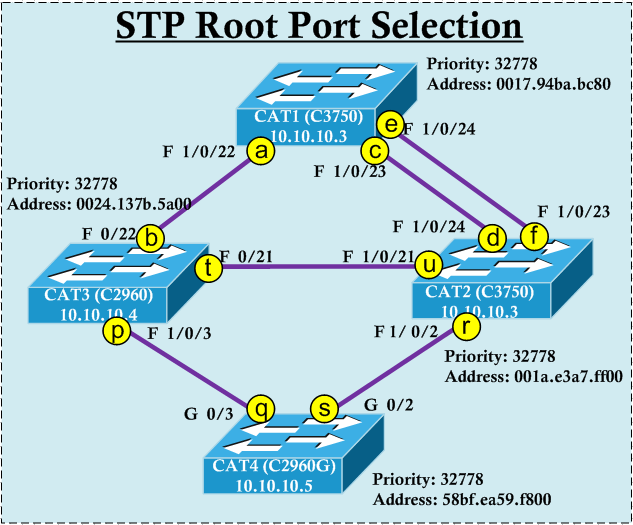
STP Root Port Selection
In this post we will see how to manipulate STP root port selection in a given topology. We will use the VLAN 10 (management vlan) STP instance to see which ports will be Root Port in each switch. Any given switch Bridge ID consist of Bridge Priority (default 32768 + system extend ID) & MAC address. Since we are taking vlan10 as example default bridge priority will be 32778.
Here are the basic rules of STP
1. Lowest bridge ID (Priority:MAC Address) switch becomes the Root-Bridge
2. Each non-root bridge should have ONE root port (RP) which is the port having lowest path-cost to Root Bridge.
3. All ports in Root Bridge become Designated Ports (DP)
4. Each segment should have one Designated Port (DP)
5. All RP/DPs will be in FORWARDING state & all other ports will be in BLOCKING state.
According to the topology CAT1 is having lowest MAC address (hence lowest bridge ID) & will become the Root Bridge. Butif you do not want to rely on MAC addreses you can lower priority of a given switch to make them as the Root Bridge for all VLANs. In my case will make priority for all Vlans to lowest value( which is 0) in CAT1.
CAT1(config)#spanning-tree vlan 1-4094 priority ?
  <0-61440>  bridge priority in increments of 4096

CAT1(config)#spanning-tree vlan 1-4094 priority 0
CAT1#sh spanning-tree vlan 10
VLAN0010
  Spanning tree enabled protocol ieee
  Root ID    Priority    10
             Address     0017.94ba.bc80
             This bridge is the root
             Hello Time   2 sec  Max Age 20 sec  Forward Delay 15 sec

  Bridge ID  Priority    10     (priority 0 sys-id-ext 10)
             Address     0017.94ba.bc80
             Hello Time   2 sec  Max Age 20 sec  Forward Delay 15 sec
             Aging Time  300 sec
Now we will look at which port become Root Port in each non-root bridges (CAT2,CAT3,CAT4). Root Port selection is based on the port having lowest cost to the Root Bridge (CAT1). For PVST (Per VLAN Spanning Tree) path cost will depend on bandwidth of links and cost value is as shown below for most commonly used links.
10Gbps -> 2
1 Gbps -> 4
100 Mbps -> 19
10 Mbps -> 100
1 Gbps -> 4
100 Mbps -> 19
10 Mbps -> 100
Also it is important to understand how path cost calculate. From Root Bridge it will send BPDU with cost to Root Bridge as “0”. When this BPDU receive by any other switch it will add its own port cost (according to the above mentioned value). So if BPDU receive by a Fast Ethernet port (100 Mbps) it will calculate path cost to root as 19 (0+19).
For CAT3, it has 3 different option (label b,t,p). Here Root Port choice is obvious, only via Fa 0/22 (b) is having lowest path cost to Root Bridge. So that will become the Root Port.
For CAT2’s it has 4 different ports (label d,f,u,r). Out of which two ports (d & f) are having same path cost (19) to Root Bridge. Via port “u” it is having path cost of 38 & via port “r” it is having path cost of 57. Since we have two equal cost paths, you need to know tie breaking rules in this scenario. Here they are,
1. Lowest Sending Bridge ID2. Lowest Port Priority (of sender)3. Lowest Interface number (of sender)
In our case both port “d” & “f” receiving BPDU from same bridge (CAT1) which suggest “lowest port priority of sender” will be the tie breaker. By default each port is having priority value of 128 (can be 0-256 multiplier of 16). This makes “lowest interface number of sender” it tie breaker. In our case CAT1’s fa1/0/23 is having lower interface number & therefore that BPDU received by CAT2’s fa1/0/24 will become root port.
CAT2#sh spanning-tree vlan 10
VLAN0010
  Spanning tree enabled protocol ieee
  Root ID    Priority    10
             Address     0017.94ba.bc80
             Cost        19
             Port        26 (FastEthernet1/0/24)
             Hello Time   2 sec  Max Age 20 sec  Forward Delay 15 sec

  Bridge ID  Priority    32778  (priority 32768 sys-id-ext 10)
             Address     001a.e3a7.ff00
             Hello Time   2 sec  Max Age 20 sec  Forward Delay 15 sec
             Aging Time  15  sec

Interface           Role Sts Cost      Prio.Nbr Type
------------------- ---- --- --------- -------- --------------------------------
Fa1/0/2             Desg FWD 19        128.4    P2p
Fa1/0/21            Desg FWD 19        128.23   P2p
Fa1/0/23            Altn BLK 19        128.25   P2p
Fa1/0/24            Root FWD 19        128.26   P2p
Now let’s see what will happen if you change CAT1’s fa1/0/24 port priority.
CAT1(config-if)#spanning-tree vlan 10 port-priority ?
  <0-240>  port priority in increments of 16

CAT1(config-if)#spanning-tree vlan 10 port-priority 0

CAT1(config-if)#do sh span vlan 10
Interface           Role Sts Cost      Prio.Nbr Type
------------------- ---- --- --------- -------- --------------------------------
Fa1/0/22            Desg FWD 19        128.24   P2p
Fa1/0/23            Desg FWD 19        128.25   P2p
Fa1/0/24            Desg FWD 19          0.26   P2p
Now if you look in CAT2 you would see Fa1/0/23 (connected to CAT1’s fa1/0/24) will become root port because of the lower port priority of sender.
CAT2#sh spanning-tree vlan 10
VLAN0010
  Spanning tree enabled protocol ieee
  Root ID    Priority    10
             Address     0017.94ba.bc80
             Cost        19
             Port        25 (FastEthernet1/0/23)
             Hello Time   2 sec  Max Age 20 sec  Forward Delay 15 sec

  Bridge ID  Priority    32778  (priority 32768 sys-id-ext 10)
             Address     001a.e3a7.ff00
             Hello Time   2 sec  Max Age 20 sec  Forward Delay 15 sec
             Aging Time  15  sec

Interface           Role Sts Cost      Prio.Nbr Type
------------------- ---- --- --------- -------- --------------------------------
Fa1/0/2             Desg FWD 19        128.4    P2p
Fa1/0/21            Desg FWD 19        128.23   P2p
Fa1/0/23            Root FWD 19        128.25   P2p
Fa1/0/24            Altn BLK 19        128.26   P2p
For CAT4, both port G0/3 “q” & G0/2 “s” are having equal path cost(38) to root bridge(CAT1). But in this case port “s” is getting BPDU from a lower bridge id switch CAT2 (32778: 001a.e3a7.ff00) comparison to port “q” from CAT3 (32778: 0024.137b.5a00). In this case Port “s” – G0/2 become root port & Port Priority or Interface ID won’t come into play.
CAT4#sh span vlan 10
VLAN0010
  Spanning tree enabled protocol ieee
  Root ID    Priority    10
             Address     0017.94ba.bc80
             Cost        38
             Port        2 (GigabitEthernet0/2)
             Hello Time   2 sec  Max Age 20 sec  Forward Delay 15 sec

  Bridge ID  Priority    32778  (priority 32768 sys-id-ext 10)
             Address     58bf.ea59.f800
             Hello Time   2 sec  Max Age 20 sec  Forward Delay 15 sec
             Aging Time  15  sec

Interface           Role Sts Cost      Prio.Nbr Type
------------------- ---- --- --------- -------- --------------------------------
Gi0/2               Root FWD 19        128.2    P2p
Gi0/3               Altn BLK 19        128.3    P2p
But in here if you want to make G0/3 as root port you can change it’s port cost to a lower value which results lower path cost to root. In this example I will change it to cost of 1 which resulting path cost to root is 20 via that port. So that will become root port.
CAT5(config-if)#spanning-tree vlan 10 cost ?
  <1-200000000>  Change an interface's per VLAN spanning tree path cost

CAT5(config-if)#spanning-tree vlan 10 cost 1

CAT5#sh spanning-tree vlan 10
VLAN0010
  Spanning tree enabled protocol ieee
  Root ID    Priority    10
             Address     0017.94ba.bc80
             Cost        20
             Port        3 (GigabitEthernet0/3)
             Hello Time   2 sec  Max Age 20 sec  Forward Delay 15 sec

  Bridge ID  Priority    32778  (priority 32768 sys-id-ext 10)
             Address     58bf.ea59.f800
             Hello Time   2 sec  Max Age 20 sec  Forward Delay 15 sec
             Aging Time  300 sec

Interface           Role Sts Cost      Prio.Nbr Type
------------------- ---- --- --------- -------- --------------------------------
Gi0/2               Altn BLK 19        128.2    P2p
Gi0/3               Root FWD 1         128.3    P2p
Now you know which port becomes a root port in each non-root switches. So Port “b”, “f” & “q” will become root port in this topology. If you want to identify which ports become Designated Ports (DP) you can follow below rules.
1. All ports in Root Bridge will become Designated Ports
2. Each segment (link) will have ONE Designated Port.
2. Each segment (link) will have ONE Designated Port.
If a given link does not have a Root Port, either of them could be a designated port. But lower bridge ID switch port wins in this situation (“u” in “t-u” link & “r” in “r-s” link ) become a DP. In this way ports other than “d”, “t” & “s” will become either DP or RP. Hence those will become “FORWARDING” ports & others (d,t,s) become “BLOCKING” Ports as shown in the below diagram.

Here is “show spanning tree vlan 10” output to verify the above.
CAT2#sh spanning-tree vlan 10
Interface           Role Sts Cost      Prio.Nbr Type
------------------- ---- --- --------- -------- --------------------------------
Fa1/0/2             Desg FWD 19        128.4    P2p
Fa1/0/21            Desg FWD 19        128.23   P2p
Fa1/0/23            Root FWD 19        128.25   P2p
Fa1/0/24            Altn BLK 19        128.26   P2p <- "port d"

CAT3#sh spanning-tree vlan 10
Interface           Role Sts Cost      Prio.Nbr Type
------------------- ---- --- --------- -------- --------------------------------
Fa0/3               Desg FWD 19        128.3    P2p
Fa0/21              Altn BLK 19        128.21   P2p <- "Port t"
Fa0/22              Root FWD 19        128.22   P2p

CAT4#sh spanning-tree vlan 10
Interface           Role Sts Cost      Prio.Nbr Type
------------------- ---- --- --------- -------- --------------------------------
Gi0/2               Altn BLK 19        128.2    P2p <- "port S"
Gi0/3               Root FWD 1         128.3    P2p
In this way you can manipulate the Root Port selection of your network.
Ссылка на оригинал
https://mrncciew.com/2013/07/07/stp-root-port-selection/
четверг, 22 декабря 2016 г.
PPP Peer neighbor route - для чего?
PPP has something called peer neighbor route. It installs a /32 route for the neighbors IP address which can be seen as connected. That is why it succeeds. You can disable the peer neighbor route per interface with no peer neighbor-route command.
Возьмем к примеру такую схему.

Возьмем к примеру такую схему.

The ping was succeeded between these two routers with ppp encapsulation . what is the reason for that ?
with HDLC
Gateway of last resort is not set
C 10.0.0.0/8 is directly connected, Serial0/0/0
with PPP
Gateway of last resort is not set
C 10.0.0.0/8 is directly connected, Serial0/0/0
20.0.0.0/32 is subnetted, 1 subnets
C 20.1.1.1 is directly connected, Serial0/0/0
Peer neighbor route is a PPP feature that allows for connected interfaces that are not on the same IP subnet to communicate with one another.
Default behavior on Cisco routers using PPP encapsulation.
Example: R1----10.1.1.1/24------------------10.2.2.2/24-------R2
R1#sh ip route connected
10.0.0.0/24 is subnetted, 1 subnets
C 10.1.1.0 is directly connected, Serial1/0
Note its only showing R1's connected network Because HDLC encapsulation
R1#sh int s1/0 | in HDLC
Encapsulation HDLC, crc 16, loopback not set
Change it to PPP now.
RX(config)#int s1/0
RX(config-if)#encapsulation ppp
R1#sh int s1/0 | in PPP
Encapsulation PPP, LCP Open
R1#sh ip route connected
10.0.0.0/8 is variably subnetted, 2 subnets, 2 masks
C 10.2.2.2/32 is directly connected, Serial1/0
C 10.1.1.0/24 is directly connected, Serial1/0
This happen because of the IPCP (Internet Protocol Control Protocol), the router installed the route 10.2.2.2 into the IP routing table.Lets debug and verify it.
R1#debug ppp negotiation
PPP protocol negotiation debugging is on
*Apr 28 23:37:15.479: Se1/0 IPCP: Address 10.1.1.1 (0x03060A010101)
*Apr 28 23:37:15.479: Se1/0 CDPCP: O CONFREQ [Closed] id 1 len 4
*Apr 28 23:37:15.483: Se1/0 PPP: Process pending ncp packets
*Apr 28 23:37:15.483: Se1/0 IPCP: Redirect packet to Se1/0
*Apr 28 23:37:15.483: Se1/0 IPCP: I CONFREQ [REQsent] id 1 len 10
*Apr 28 23:37:15.483: Se1/0 IPCP: Address 10.2.2.2 (0x03060A020202)
*Apr 28 23:37:15.487: Se1/0 IPCP: O CONFACK [REQsent] id 1 len 10
*Apr 28 23:37:15.487: Se1/0 IPCP: Address 10.2.2.2 (0x03060A020202)
*Apr 28 23:37:15.491: Se1/0 IPCP: I CONFACK [ACKsent] id 1 len 10
*Apr 28 23:37:15.491: Se1/0 IPCP: Address 10.1.1.1 (0x03060A010101)
*Apr 28 23:37:15.495: Se1/0 IPCP: State is Open
*Apr 28 23:37:15.495: Se1/0 CDPCP: I CONFACK [REQsent] id 1 len 4
*Apr 28 23:37:15.503: Se1/0 IPCP: Install route to 10.2.2.2
*Apr 28 23:37:17.455: Se1/0 CDPCP: Timeout: State ACKrcvd
*Apr 28 23:37:17.539: Se1/0 CDPCP: State is Open
Вывод:
the PPP peer neighbour route is useful when each end of the PPP link is on a different subnet like when using ip unnumbered interfaces( borrowing the IP address from another interface for the PPP interface).
if both ends are on same subnet then you can safely disable the peer neighbour route.
среда, 21 декабря 2016 г.
Группа исходящих dial-peer как destination для входящего dial-peer
Группа исходящих dial-peer как destination для входящего dial-peer
(Outbound Dial-Peer Group as Inbound Dial-Peer Destination)
Эта функция позволяет в конфигурации входящего dial-peer указать группу исходящих dial-peer как цель маршрутизации входящего звонка. Поддерживается, начиная с IOS 15.4(1)T.
Если входящий звонок попадает во входящий dial-peer, в котором есть активная группа исходящих dial-peer, то для маршрутизации этого звонка будут выбраны dial-peer из указанной группы. Другие dial-peer никогда не будут использоваться как исходящие для этого звонка. Даже если в указанной группе все dial-peer в состоянии down.
В группу можно объединить до 20 dial-peer (как SIP так и H323). Так же, каждому dial-peer можно указать его приоритет в группе, что будет влиять на выбор dial-peer для установления исходящего звонка.
Пример конфигурации:
Пример конфигурации:
CUBE-1(config)# dial-peer voice 1 voip
CUBE-1(config-dial-peer)# destination-pattern 0[2-5]......
CUBE-1(config-dial-peer)# session protocol sipv2
CUBE-1(config-dial-peer)# session target ipv4:10.1.1.1
CUBE-1(config)# dial-peer voice 2 voip
CUBE-1(config-dial-peer)# destination-pattern 00..........
CUBE-1(config-dial-peer)# session protocol sipv2
CUBE-1(config-dial-peer)# session target ipv4:10.1.1.1
CUBE-1(config)# dial-peer voice 3 voip
CUBE-1(config-dial-peer)# description vip
CUBE-1(config-dial-peer)# destination-pattern 0.T
CUBE-1(config-dial-peer)# session protocol sipv2
CUBE-1(config-dial-peer)# session target ipv4:10.10.10.10
Первые 2 dial-peer используются для маршрутизации всех городских и междугородних вызовов. В третий dial-peer могут маршрутизироваться вызовы только с определенных номеров, это vip подключение.
Наша задача разделить звонки по правильным направлениям.
2. Создаем 2 группы исходящих dial-peer
CUBE-1(config)# voice class dpg 200
Группа 200 будет использоваться для маршрутизации VIP звонков. В приоритете dial-peer 3, если через него звонок не получится установить – будем использовать общий канал (dial-peer 1).
Группа 100 для всех остальных звонков. Здесь мы приоритеты не указывали. Как же будет происходить выбор dial-peer в группе? Логично предположить, что по значению destination-pattern. Но нет! В данном случае этот критерий вообще не учитывается. Выбор выполняется на основании значения dial-peer hunt. По дефолту – random.
Варианты:
2. Создаем 2 группы исходящих dial-peer
CUBE-1(config)# voice class dpg 100
!Создаем группу dial-peer с номером 100
!Создаем группу dial-peer с номером 100
CUBE-1(config-class)# dial-peer 1
!Добавляем в эту группу нужные нам dial-peer
!Добавляем в эту группу нужные нам dial-peer
CUBE-1(config-class)# dial-peer 2
CUBE-1(config-class)# description All_calls
CUBE-1(config)# voice class dpg 200
CUBE-1(config-class)# dial-peer 3 preference 1
!Указываем приоритет dial-peer в группе. Диапазон 0-10. 0 - самый высокий приоритет, 10 - самый низкий
!Указываем приоритет dial-peer в группе. Диапазон 0-10. 0 - самый высокий приоритет, 10 - самый низкий
CUBE-1(config-class)# dial-peer 1 preference 5
CUBE-1(config-dial-peer)# session target ipv4:10.10.10.10
Группа 200 будет использоваться для маршрутизации VIP звонков. В приоритете dial-peer 3, если через него звонок не получится установить – будем использовать общий канал (dial-peer 1).
Группа 100 для всех остальных звонков. Здесь мы приоритеты не указывали. Как же будет происходить выбор dial-peer в группе? Логично предположить, что по значению destination-pattern. Но нет! В данном случае этот критерий вообще не учитывается. Выбор выполняется на основании значения dial-peer hunt. По дефолту – random.
Варианты:
CUBE-1(config)# dial-peer hunt ?
<0-7> Dial-peer hunting choices, listed in hunting order within each choice:
0 - Longest match in phone number, explicit preference, random selection
1 - Longest match in phone number, explicit preference, least recent use
2 - Explicit preference, longest match in phone number, random selection
3 - Explicit preference, longest match in phone number, least recent use
4 - Least recent use, longest match in phone number, explicit preference
5 - Least recent use,explicit preference, longest match in phone number
6 - Random selection
7 - Least recent use
Исходя из этого, разницы между моими dial-peer 1 и dial-peer 2 нет, так как отличаются они только параметром destination-pattern.
3. Создаем входящие dial-peer
CUBE-1(config)# dial-peer voice 100 voip
!Указываем созданную ранее группу как цель маршрутизации звонка, попавшего в данный dial-peer
4. Проверяем
CUBE-1# show voice class dpg 200
Оригинальная статья здесь
3. Создаем входящие dial-peer
CUBE-1(config)# dial-peer voice 100 voip
CUBE-1(config-dial-peer)# answer-address .
CUBE-1(config-dial-peer)# destination dpg 100!Указываем созданную ранее группу как цель маршрутизации звонка, попавшего в данный dial-peer
CUBE-1(config)# dial-peer voice 200 voip
CUBE-1(config-dial-peer)# answer-address 555.
!Наши VIP абоненты (номера с 5550 по 5559)
!Наши VIP абоненты (номера с 5550 по 5559)
CUBE-1(config-dial-peer)# destination dpg 200
CUBE-1# show voice class dpg 200
Voice class dpg: 200 AdminStatus: Up
Description: VIP_calls
Description: VIP_calls
Total dial-peer entries: 2
Peer Tag Pref
-------- ----
3 1
1 5
-------------------------------------
-------------------------------------
CUBE-1# show dial-peer voice 200 | include destination dpg
destination dpg tag = 200 status = valid,
Оригинальная статья здесь
Хорошего дня!
Подписаться на:
Комментарии (Atom)